Introduction to Networking and Networking Models
Know and understand the fundamentals!
OSI Networking Model
Layer 7 – Application Layer: Where users interact with the network. Authentication runs here, but encryption runs on layer 6. Ensures foreign partner is available; resources exist and that they agree on data integrity, privacy and error recovery procedures.
Layer 7 Protocols: Email, SMTP and POP3, Telnet, Http, FTP, SNMP.
Layer 6 – Presentation Layer: Answers “How should this data be presented?”. Formats data. Encryption occurs at this layer. Four primary tasks, compatibility with the operating system, proper encapsulation of data for transmission, data formatting (ASCII, Binary), data encryption, compression and translation.
Layer 6 File Types: Jpeg, gif, tiff, etc
Layer 5 – Session: The “manager” of two-way communication between 2 hosts. Handles Creation, maintenance and tear down of communications between two hosts. Overall communication is called a session.
Layer 4 – Transport: Purpose is to establish end-to-end communication, segment data received from upper layers, ensure data arrives in the correct order and free of errors. Two methods of transporting data: connection-oriented (TCP) and connectionless (UDP)
Layer 3 – Network: IP runs at this layer, routers operate here, often called “routeing layer”. Routing simplified: “What paths exist?”, “What is the best path?”
Layer 2 – Switches, Wireless AP, Cable and DSL modems run here. 4 major specifications run here: Ethernet, HDLC, PPP and Frame Relay. This layer does perform error detection but not error recovery. Mac addresses are layer two addresses.
Layer 1 – Physical: “Its all Ones and Zeros” Actual transmission of data, the circuits, pins cables and connections are all layer 1.
Data Transmission Process
Application, Presentation and Session layers, data is simply called “data”.
The transport layer, data is placed into segments.
Network layer, data is placed into packets.
Data Link Layer, data is placed into frames.
Physical layer, data takes the form of bits
As data flows down the OSI model each layer adds a header that will be removed by the same layer on the other end of the session, these headers are layer specific and are only read by the same layer at the other end. Note: the data link layer and a header AND a trailer.
Protocol Data Unit (PDU): Combination of data and a layer specific header. A PDU exists for each layer, e.g. Layer 7 PDU. Once the data is received and heads up the OSI model, each layer removes its header added by its counterpart. L3 removes L3
Same Layer Interaction: Process of OSI layer removing the header placed on the data on the same layer on the sending side.
Adjacent Layer Interaction: Interaction between layers on the same host. The application interacts with presentation etc.
TCP/IP Networking Model
Alternative to OSI, only uses four layers. Application, Transport, Internet and Network Access.
Application: Maps to the top 3 layers of the OSI Model
Transport: Maps directly to the transport layer of the OSI model
Internet: Maps directly to the Network layer of the OSI model
Network Access: Maps to the data link and the physical layers of the OSI model.
TCP and UDP
TCP: Guaranteed deliver, Error Detection and Recovery with Sequence and ACK numbers, Windowing, “Connection-Oriented”.
UDP: “Best Effort” delivery, but no guarantee of delivery, No error detection, No windowing, “Connectionless.
TCP’s Three Way Handshake
Negotiation of parameters before segments are sent with TCP/IP is 3-way handshake Not used by UDP.
First, an SYN packet is sent to negotiation the TCP Sequence Number.
Recipient responds with a: SYN / ACK (synchronisation, acknowledgement)
The Sender responds with an ACK. Handshake complete.
Also uses a FIN (finish) bit to end channel when communication is closed.
TCP’s Error Detection / Error Recovery Feature.
Error detection is finding an error; Error recovery is fixing it.
TCP does both by using the SYN number, ACK number and TCP Header.
The host sends data in segments, each segment has a sequence number, the sequence number contains the order to reassemble the segments. Once receive the recipient sends a segment back with no data except an ACK number. The ACK number is the next segment the recipient expects.
If a segment has been lost, the recipient will send an ACK saying it is expecting to receive a segment that the sender has already sent. (error detection) The sender then re sends the segment that the recipient is expecting.(error recovery).
If the ACK is lost? The sender sets an ACK timer. If an ACK is not received before the timer expires, it resends all segments.
The Process (Positive acknowledgement with retransmission) sender is waiting for a message that data was received. If the message is not received then data is retransmitted.
Windowing: Amount of data that can be sent without waiting for an ACK. The recipient decides the size of the window, not the sender. Gives the recipient “flow control”. If no errors are detected the recipient will increase the window size, if it starts to see errors it will decrease the window size. This dynamic adjustment is called “sliding window”. UDP does not have windowing capabilities.
Why use UDP?
The UDP header is much smaller. No SYN / ACK field or bit. No Window Field.
The TCP and UDP headers have only 3 values in common source port, destination port, checksum. Due to smaller header UDP has much less overhead.
Source and Destination Ports
To differentiate different data being sent since the MAC and IP will be the same they will have different Port numbers. This is called Multiplexing. All Port numbers below 1024 are reserved.
Standard TCP Ports
FTP – File Transfer Protocol – Uses TCP ports 20 and 21
- SSH – Secure Shell – Uses TCP port 22.
- Telnet uses TCP port 23.
- SMTP – Simple Mail Transfer Protocol – uses TCP port 25.
- HTTP – Hypertext Transfer Protocol – uses TCP port 80.
- POP3 – Post Office Protocol 3 – uses TCP port 110.
- SSL – Secure Socket Layer – Uses TCP port 443.
Some Common UDP Ports:
- DHCP – Dynamic Host Control Protocol – Uses UDP ports 67 and 68
- TFTP – Trivial File Transfer Protocol – uses UDP port 69
- SNMP – Simple Network Managment Protocol – Uses UDP port 161.
Protocols Using both TCP and UDP Ports
- DNS – Domain name service – uses UDP and TCP port 53.
- The port number 24 is reserved in both UDP and TCP for private mail systems.
Voice over IP (VoIP): The entire range of UDP ports from 16384 – 32767 are reserved for voice traffic.
Socket
The socket is a combination of IP address and port number. For example, 10.1.1.2 on port 69 is 10.1.1.2:69.Ethernet Standards and Cable Types
CSMA/CD – Carrier Sense Multiple / Collision Detection
Used to prevent collision when data is being transferred on a shared bus. Before a host sends data is listens to the wire to see if other hosts are transmitting, if not then it will transmit data. If that happens at the same time a collision will occur, this will change the physical voltage on the line, all hosts will sense this then send a jam signal onto the wire indicating to other hosts not to send anything. To prevent another collision both hosts invoke a random back off timer which is set in milliseconds before they retransmit after listening to the wire again.
The more hosts on a wire the higher possibility of a collision. Not common now as most networks use switches.
Ethernet Standard
10Base-T specified by IEEE 802.3 – T stands for twister pair. Maximum length is 100 meters. The 10 refers to 10Megabits per second. Twisting pairs custs down electromagnetic interference.
First Ethernet standards 10Base5 and 10Base2 were usually used on shared bus network topology. Ethernet is considered logical bus topology. Limit of 10base5 is 500 meters, 10Base2 is 185 meters.
Ethernet runs at 10MBPS, defined by IEEE 802.3, maximum cable length of 100 meters. Variations include 10Base-T, 10Base02 and 10Base-5, with the last two involving a shared cable bus.
Fast Ethernet runs at 100MBPS, is defined by IEEE 802.3u and has a maximum cable length of 100 meters.
Gigabit Ethernet runs at 1000MBPS (1GBPS), is defined by IEEE 802.3z and 802.ab . and also has a 100-meter maximum cable length, but it cannot use copper cabling.
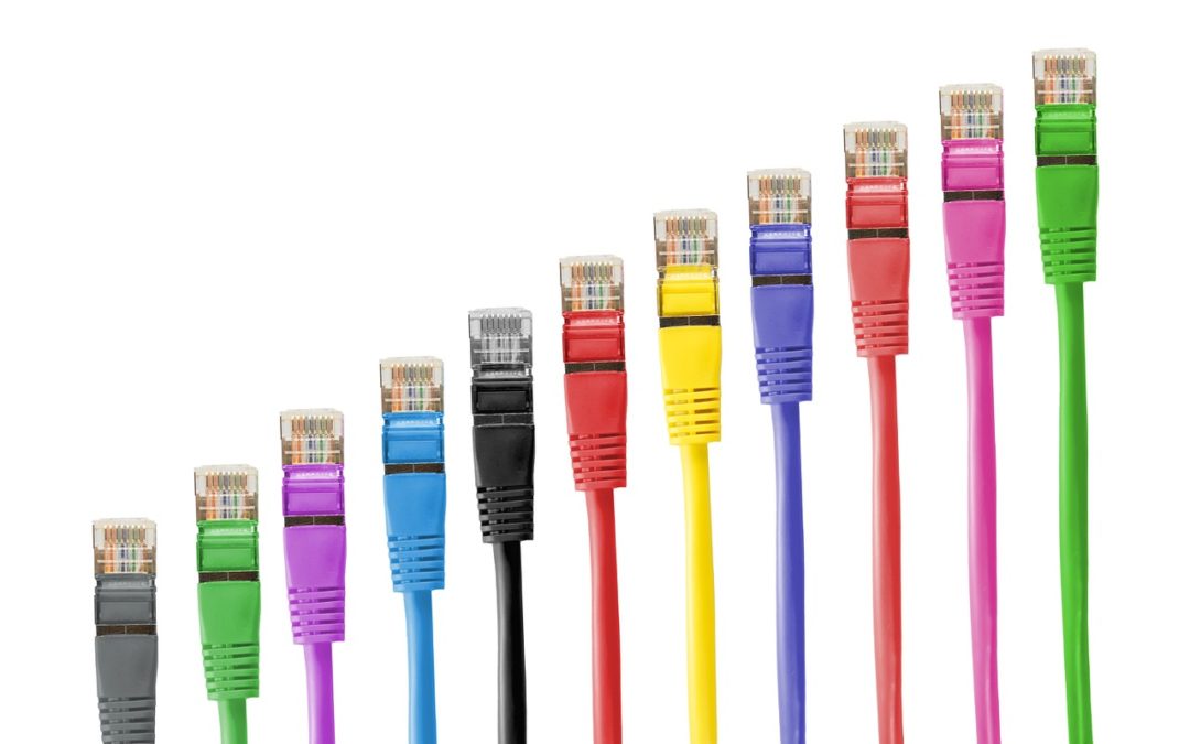
Ethernet Cables
Standard Ethernet cabling is a cat5 unshielded twisted pair (Cat5 UTP) with an RJ45 connector with eight pins. Pins 1 and 2 transmit, pins 3 and six receive.
Crosstalk
Caused by electromagnetic interference when signal crosses over from one pair of cables to another. NEXT (Near end cross talk) is a condition caused by crossed or crushed pairs of wires. In typical RJ-45 crosstalk is at its highest as data enters the cables. PSNEXT (Power sum near end cross talk) refers to calculation carried out when NEXT test is run.
Straight through cable
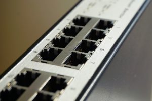
Used to connect a PC to a switch or Hub
Crossover Cable
Used for trunking switches and connecting PC to PC.
Rollover Cable
All pins “rollover”, one end of the cable is DB9.
Ethernet / NIC / Physical / LAN / BIA / Mac addressing
Above names all refer to MAC (Media Access Control) address. Used by switches to send frames. 48 Bit hexadecimal address. Split into two parts, first is Organizationally Unique Identifier (OUI) that is assigned to hardware vendors by IEEE. OU comprises first half. Second half is a value not yet used by the vendor.
Broadcast MAC Address is all F’s. There is a range of multicast MAC addresses, and the first half of a multicast MAC address is always 01-00-5E . The Second Half of a multicast mac address will fall in the range 00-00-00 through 7F-FF-FF.
Wan Cabling
Cisco routers will use serial cables for connections using their serial interfaces (typically frame relay)
Switching
Repeaters: Repeats the electrical signal, takes incoming signal and creates a copy, wards of cable attenuation, increases max cable lengths, works on the physical layer.
Hubs: basically same as a repeater but with more ports. Only operates at physical layer. Only one device transmits at a time, resulting in shared bandwidth and need for CSMA/CD. A group of workstations linked together by only a hub creates a “collision domain”.
Bridges: Seperates collision domains, typically placed between multiple repeaters and hubs. Creates smaller collision domains but still one big broadcast domain.
Micro Segmentation: Is a term to describe the “one host, one collision domain” effect.
Mac Address Table: Also CAM (Content Addressable Memory) table, bridging table, switching table, mac table.
Switches: Cisco switch can do three things with an incoming frame, Forward it, Flood it or Filter it. To decide it consults its mac address table for an entry for the source mac address and then the destination mac address.
Flooding is performed when the switch has no entry for the destination MAC address. Flooding is sending out the frame on every single port except the one it came in on. Unkown unicast frames are always flooded.
Forwarding is performed when the switch does have an entry for the frames destination MAC. Frame is sent out on one port.
Filtering is when the swith has an entry for both source and destination mac and both are on the same port.
Switches never send a frame back on the same port it came in on.
Forwarding: When a frame is forwarded it has three processing options. Store and forward, cut through and fragment free.
Store and forward: Entire frame is stored, checks FCS before forwarding. Method gives the most error detection (not recovery)
Cut Through: Only Mac Addresses are read before forwarding. Faster but no error detection.
Fragment Free: First 64 bytes of incoming frame are checked for errors. Offers a balande between speed and error detection.
Broadcast Storm: By defaulta switch is one broadcast domain, also default is when a broadcast is sent the switch will send a broadcast and host will usually respond by sending a broadcast. This continual generation of new broadcasts (The broadcast storm) can overwhelm a switch rendering it useless.
VLANS: Creating more vlans will create less broadcast domains. No traffic can be sent from one vlan to another withouth the intervention of a layer 3 device.
Three Layer Switching Model: Cisco switching model has three layers, access, distribution and core.
Spanning Tree Protocol: Cisco switches use the Spanning Tree Protocol enabled by default to prevent switching loops. STP determines loop free path for frames and ports. Frames and ports not on that path will be placed into blocking mode.
Basic Switch Security: Physically Lock up switches. Unused VLANS are a security feature. Default Cisco switch ports have undesirable defaults, ports are open, actively attempting to trunk, all ports are in vlan1.
Port Security: Switch inspects the source MAC address of an incoming frame, if considered secure the user will be able to access the network, if unsecure the port will take one of several actions. Default is Shutdown; the port will then be error-disabled and will have to be manually reopened. Restrict drops the violating frames and logs the issue. Protect simply drops the frames.
Common Router and Switch Commands
Password protect console port login: conf t, line console 0, password (password), login.
Password protects telnet VTY lines: conf t, line vty 0 15, password (password), login.
Password protect privileged level: conf t, enable secret (password)
. If a user connects via telnet this is mandatory.
Secure Shell: All data sent via telnet is un encrypted (including passwords). SSH is encrypted, to setup we need to create a user name / password database.
conf t, line cty 0 4, login local.
username (username) password (password)
Also a domain name must be specified in the ip domain-name command, a crypto key must be created with the crypto key generate rsa command.
LED Indicators: Green = Good, Amber only indicates a problem if it doesn’t go away, dark red is bad.
SYST, green is on, no means it isn’t. Amber is POST failure.
RPS: Redundant Power Supply.
STAT: Short for Status
DUPLEX: Green indicates full duplex, off means half duplex.
SPEED: Where solid green indicates 100MBPS , off indicates 10MBPS and flashing green 1000MBPS
VLAN 1: Conf t, interface vlan1, IP address (IP) (subnet). Assign as default gateway: conf t, IP default-gateway (IP address).
Interface Range: Conf t, interface range fast 0/1 – ?. (after that all commands you enter will be applied to the range of ports.
Banner: Before login screen: banner motd $ (enter), To display on login: banner login $ (enter), To display after successful login: banner exec $ (enter)
“Logging Synchronous” and “exec-time-out 0 0” commands
Loggin Synchronus tells the router to hold messages until it detects no input from the keyboard and no output from the router.
IP Addressing and the Routing Process
192.168.1.100
128 64 32 16 8 4 2 1
192 1 1 0 0 0 0 0 0 11000000
168 1 0 1 0 1 0 0 0 10101000
1 0 0 0 0 0 0 0 1 00000001
100 0 1 1 0 0 1 0 0 01100100
255.255.255.0 = 11111111 11111111 111111111 00000000
IP Classes
The Three ranges of addresses that can be assigned to hosts :
- Class A: 1 – 126
- Class B: 128 – 191
- Class C: 192 – 223
The following classes are reserved and cannot be assigned to hosts:
- Class D: 224 – 239. Reserved for Multicasting, a topic not covered on the CCNA exams.
- Class E: 240 – 255. Reserved for Future use, also called “experimental addresses”.
- Any address with the first octet of 127 is reserved for loopback interfaces. This range is *not* for Cisco router loopback interfaces, though.
Class A:
- Default network mask: 255.0.0.0
- Default number of network bits: /8
- Default number of host bits: 24
Class B:
- Default network mask: 255.255.0.0
- Default number of network bits: /16
- Default number of host bits: 16
Class C:
- Default network mask: 255.255.255.0
- Default number of network bits: /24
- Default number of host bits: 8
Address classes A,B, and C all have their own reserved range of addresses. You should be able to recognise an address from any of these ranges immediately.
- Class A: 10.0.0.0 – 10.255.255.255
- Class B: 172.16.0.0 – 172.31.255.255
- Class C: 192.168.0.0 – 192.168.255.255
You should be able to identify those ranges in that format, or with the dotted decimal masks, or with prefix notation. More about prefix notation later in this section.
- Class A: 10.0.0.0 255.0.0.0 or 10.0.0.0 /8
- Class B: 172.16.0.0 255.240.0.0 or 172.16.0.0 /12
- Class C: 192.168.0.0 255.255.0.0 or 192.168.0.0 /16
The /8. /12 and /16 denotes the number of 1’s at the beginning of the mask.
If 192.168.1.100 wants to send packets to the host at 10.1.1.5, the sending host knows it’s not on the same subnet as 10.1.1.5. In that case the host will send the packets to its default gateway. The host is basically saying “I have no idea where this address is so ill send it to my default gateway and let that device figure it out.”
When a router receives a packet, there are three actions regarding its destination:
- Destined for a directly connected network
- Intended for a non-directly connected network that the router has an entry for in its routeing table.
- Destined for a non-directly connected network that the router does not have an entry for
Static Routes are created with the IP route command: up route 30.0.0.0 255.0.0.0 ethernet1
ARP, DNS and DHC
To know the IP of the DNS server, it is either hard coded or learned via DHCP.
ARP: uses a series of broadcasts and replies. If a hosts needs the MAC address of a remote device it will send out an ARP request as a layer 2 broadcast, so the source MAC address will be that of Host A. The destination MAC address will be ff-ff-ff-ff-ff-ff, the source IP address will be Host A, the destination IP will be that of host B.
To limit broadcasts the host builds ARP caches that they consult before sending out requests. They contain an IP, Mac address mapping table.
Router does not forward arp broadcasts but instead uses proxy arp to answer the arp request with the MAC address of the router interface that received the original request.
DHCP: Client sends a DHCP discover message as a broadcast, A DHCP server that receives that message will respond with a DHCP offer, if multiple offers are received the client will use the first received, When other DHCP servers see their request was not accepted they put the IP address of the other DHCP server in.
Memory Components and Configs
Rom: Read-Only Memory, Store’s bootstrap startup program, operating system and POST programs.
Flash Memory: IOS images are stored, erasable and reprogrammable ROM. Retained by the router on reload.
RAM: Stores are routing tables and running configuration. Ram contents are lost when powered down.
NV Ram: Non-Volatile Ram. NVRam holds the routers startup configuration file. Not lost on power down.
The IOS can load from flash memory (default), a tftp server or read only memory rommon. To change that order you must modify the configuration register. Once the IOS has been found the router looks for the startup config, by default it looks in nvram and then tftp. If no config is found it asks a series of questions involving basic setup.
Configuration Register Settings:
0x2102: The default. Router looks for a startup configuration file in NVRAM and for a valid IOS image in flash.
0x2142: NVRAM contents are bypassed, startup configuration is ignored.
0x2100: Router boots into ROM Monitor mode.
Intro to Wireless Networks
WAP:Wireless access point, not always needed as wireless networks can be made in ad-hoc mode(iBSS). Two kinds of infrastructure WLANS, the most common is the Basic service set (BSS) with a single AP while an Extended service set (ESS) have multiple WAP’s.
IBSS, BSS and ESS.
802.11a data rate of 25MBPs, but can reach speeds of 54MBPs, indoor range is 100 feet, operating frequency is 5GHz.
802.11b data rate of 6.5Mbps, but can reach speeds of 11Mbps. Indoor range is 100 feet. Operating frequency is 2.4Ghz.
802.11g has a typical data rate of 25MBps, a peak data rate of 54MBps, Indoor range is 100 feet, Operating Frequency is 2.4Ghz.
802.11n data rate of 200MBPs, a peak data rate of 540MBPs and an indoor range of 160 feet. Operating frequency is 2.4Ghz or 5Ghz.
Infared offers a high data rate but too short range to be practical.
Spread Spectrum: Method of spreading a signal over a range or spectrum of frequencies. One method is Frequency Hopping Spread Spectrum (FHSS) where the sender and receiver agree on the range of frequencies to use.
DSSS (Direct Sequence Spread Spectrum): Spreads the signal over the entire range of frequencies at once. 11n and 11g use this.
OFDM (Orthogonal Frequency Division Multiplexing) splits the signal and sends the signal fragments over different frequencies at the same time.Used by 11a.
Spreading the signal increases resistance to noise, allows sharing of frequency, harder to intercept.
Antenna Types: Yagi: Sends its signal in a single direction, aka directional or point to point. Omni: Sends signal in all directions aka multipoint.
CSMA/CA: Ethernet has CSMA/CD Wireless has CSMA/CA (Carrier Sense Multiple Access with Collision Avoidance. Works the same way as each other. The real difference is where they are used and on a wireless network a JAM signal will not be sent, on wireless collisions cannot be detected only avoided. While Ethernet is full duplex, wireless clients are limited to half-duplex.
Service Set Identifier (SSID): This is the name of your wireless network.
Mac Address Authentication: Similar to Cisco port security, allows a device to authentication only if its MAC address was considered secure.
Wep, WPA and Wpa2
Wired Equivilent Privacy (WEP): Problems: Clear-Test Keys, static keys, one-way authentication, encryption is easily broken. Supports open and shared key.
Wi-Fi Protected Access (WPA): Strengths: Two-way authentication, dynamic keys and stronger encryption through Temporal Key Integrity Protocol (TKIP), WPA uses an 8-byte Message integrity check (MIC), uses 802.1x pre-shared keys (PSK) for authentication.
Binary Math and Subnetting
With your number (In this case 231) work from left to right and ask if you can subtract the multiple from 231, then keep working down with the remainder. If you can subtract it then you put a 1.
128 64 32 16 8 4 2 1
231 1 1 1 0 0 1 1 1
231 – 128 = 103
103- 64 = 39
39-32 = 7
7-4 = 3
3-2= 1
1-1=0
128 64 32 16 8 4 2 1
123 0 1 1 1 1 0 1 1
Binary to decimal is the reverse.
Class A: 1-126, 8 NW Bits, 24 Host Bits
Class B: 128 – 191, 16 NW Bits, 8 Host Bits
Class C: 192 – 223, 24 NW Bits, 8 Host Bits
Class A: 255.0.0.0
Class B 255.255.0.0
Class C: 255.255.255.0
Determining the Number of Valid Subnets
Number of subnets = (2 squared by the number of subnet bits)
Now here’s the interesting part: You *may* need to subtract 2 from that result to get the correct answer.
You should subtract two from the result if:
You see no ip subnet-zero command in the configuration. This command will appear near the top of the router configuration.
The routeing protocol is classful, and that means RIPv1 or IGRP.
You should not subtract two from the result if:
The classless protocols RIPv2, EIGRP or OSPF, are in use.
The term VLSM for “Variable-Length Subnet masking” is used.
The ip subnet-zero command appears in the configuration. This is the default setting, and you’ll see it near the top of the router configuration.
Network 172.20.0.0 Subnet Mask = 255.255.255.0 (/24) (/24 means 24 consecutive 1’s at the beginning of the subnet address)
Determining the Number of Valid Hosts
To determine the number of valid host, a somewhat similar formula is used:
Valid Hosts On A Subnet = (2 squared by number of host bits) – 2
Thankfully, we always subtract the two when determining the number of valid hosts on a subnet.
Determining the Subnet Number of A Given IP Address
Given an IP Address and subnet mask, determining the subnet it resides on is accomplished by performing a Boolean AND operation. First, the IP address and its subnet mask will be converted to binary. The Boolean AND is simply a bit-by-bit comparison of the address and the subnet mask.
If both bits are 1, the result of the boolean AND is 1. If a 0 is set for that bit on either the subnet mask or IP address or both, the result of the AND is a 0.
Determining the Range of Valid Host Addresses on A Subnet
To determine the range of valid host addresses on a subnet, first determine how many overall host addresses are on that subnet. The First address in the range is the network number and is not a valid host address; the final address in the range is the broadcast address for that subnet and is not a valid host address. All addresses between the two are valid host addresses.
Meeting Stated Design Requirments
Consider this question:
“Your network uses Class B network 165.10.0.0. You need at least 150 subnets that have no more than 200 hosts apiece. Which of the following subnet masks should you use?”
A number of subnets ‘ (2 to the nth power) where n equals the number of subnet bits.
Number of valid hosts on a subnet = (2 to the nth power) – 2 where n equals the number of host bits.
Static Routing and Rip
The “Ip route” command is used to create static routes, we can create a static route to a host or network or a default static rout that is used when there is no other match in the routing table.
The syntax for static default route: IP route 0.0.0.0 0.0.0.0 172.12.123.2 Both the destination network and the mask are all zeroed in a static default route.
Static routes are not very scalable as they are not updated dynamically.
A better choice is the use of a dynamic routing protocol like RIP (Routing Information Protocol), IGRP (Integrated Gateway Routing Protocol), EIGRP (Enhanced Integrated Gateway Routing) and OSPF (Open Shortest Path First),
RIP: There are two versions of RIP. Rip v1 – Class full, no vlsm, no manual route summarization. Rip v2 – Classless, VLSM Support, Manual route summarization support. Rip updates are sent every 30 seconds, if you run command “clear ip route” it will remove the router table and force router to send updates immediately.
Wide Area Networks
Demarcation Point: Where the system responsibility passes from the network admins to the service provider. Found at the CSU/DSU. The CSU/DSU tells the router the clock rate, which is basically how fast data can be sent or received.
When it comes to the clockrate:
–The Data Communications Equipment (DCE) provides the clockrate
–The Data Terminal Equipment (DTE) receivesthe clockrate.By default, a Cisco router acts as a DTE.
Remember: Interface administratively down, manually opens. If interface is down, physical problem. If interface is up but line protocol is down that means logical issue like encapsulation mismatch or missing clockrate.
HDLC and PPP
Are layer 2 encapsulation protocols, HDLC that runs on cisco routers is cisco proprietary, so cannot be run in multivendor environments. HDLC is default encapsulation for a Cisco Serial interface. HDLC is no compression, no multilink. No PAP or CHAP.
PPP allows data compression that is performed before data is sent across the WAN. PPP multilink allows multiple physical channels to be bundled into a single logical channel. Allows PAP and CHAP authentication.
Frame Relay
Is a packet switching protocol, The packets take different paths to physical servers where they are reassembled, In contrast, circuit switching have dedicated tracks.
Nat Translation
Inside local addresses are used by hosts on the inside network to communication with other hosts on the same network. These are the addresses that are actually configured on the hosts. Inside local addresses are translated into inside global addresses. Inside global addresses are routable addresses.
Outside global addresses are the addresses that are configured, on the outside hosts. These are fully routable addresses used by internet based hosts. Finally, outside local addresses are the actual addresses of remote hosts.
ATM: The Asynchronous Transfer Mode (ATM) is unique in that it does not handle frames, as Frame Relay does.ATM places data into cells, and all ATM cells are the same size, 53 bytes -48 bytes of data and a 5-byte header.
Troubleshooting
First, check physical layer.
Crossover cables are required to connect switches for trunking.
Rollover cables are needed to connect a laptop to a console port.
You can check a devices physical connection with Cisco Discovery Protocol.
Cisco routers do not allow users to connect via Telnet or SSH by default. A password must be set on the VTY lines.
Users who connect to a router via Telnet or SSH will by default be put into user exec mode, and for those users to have access to enable mode, an enable password must be set, *or* you must configure the privilege level 15 command on the VTY lines – that will place the incoming user into enable mode immediately upon VTY authentication.
Telnet sends all data in clear text; SSH encrypts all data, including passwords, but SSH does require more configuration and possible extra hardware, depending on the size of the deployment
Two key points about administrative distance:
AD is a measure of a route’s believability. The lower the AD, the more believable the route. This is one time when bigger is NOT better!
AD only comes into play when there is a tie in the “longest match” route comparison, as shown previously.